- Visions18
- Visions17
- Visions16
- Visions15
- Visions14
-
Construction
- Node Installations Complete!
- Six on the Seafloor!
- New Segment 7
- Defining the SIA
- PN5A Successfully Deployed!
- PN 5A – Jointing Operations
- PN 5A Installation Continues
- On Site to Install PN5A
- Transit to Node 5A
- Port Call in Portland
- PN1D is Installed!
- Burial and Inspection Completed ...
- Humpbacks Visit
- Cable Burial Node PN1C
- Milestone: PN1C is Installed
- Photos of Final Inspection of P ...
- Another RSN Node is Born!
- Cable Burial Continues at Secon ...
- Second Node Installed!
- Splicing Node PN1B into Segment ...
- Recovering End of Segment 3
- Word for the Day: Persistence
- Major Milestone: First Node Ins ...
- Primary Node 1A Powered Up on D ...
- Recovering and Testing Cable Se ...
- OOI Primary Node Installation B ...
- Cable Installation Update
- Dolphins and Puffins and Molas, ...
- Day 51: Seabed Cable Lay Comple ...
- Dynamic Positioning
- Update on Cable Installation
- Completion of Segment 1 Burial
- Leaps and Bounds at the Shore S ...
- Segment 5 Installation Complete ...
- Laying Segment 5
- Bustling Shore Station
- At-Sea Installation Phases
- Installing the Land Cable
- TE SubCom Dependable Propulsion ...
- Divers at Work
- The Day After
- Second OOI Cable Landed
- Second Cable Landing Reschedule ...
- OOI Open House in Pacific City, ...
- The Cable has Landed!
- Last Grapnel Run Before Landing ...
- Preparing for the Cable Landing ...
- Seaplow 101
- Marine Mammal Observations
- Communicating with a Fishing Ve ...
- Cable Deployment Update
- Off Pacific City, Oregon
- Finished with First Segment
- Deploying Repeaters
- Start of First Cable Segment
- Leaving Astoria
- Meeting the Cable Ship in Astor ...
- Cable Laying Vessel Underway
- Photos of OOI Cable Loading
- Northern conduit installed
- Northern Conduit drilling compl ...
- Bubble test for the Southern Co ...
- Drilling of the Northern Condui ...
- Update on Drilling
July 2013
May 2013
December 2012
October 2012
August 2012
July 2012
April 2012
March 2012
January 2012
October 2011
September 2011
August 2011
July 2011
June 2011
March 2011
February 2011
October 2010
June 2010
May 2010
April 2010
- Visions13
- Visions12
- Visions11
- Enlighten
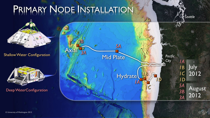
For those of us on the OOI RSN team who, like me, have been working on the project for over three years, it is exciting and personally satisfying when a node is powered from the shore station for the first time and the node performs exactly as designed. Yesterday's installation of Primary Node 1C was no exception. We now have three nodes deployed and four to go.
Here's a recap of work leading up to the July 27 deployment of this third node to a depth of 615 meters:
On Friday, July 27, during cable balancing (see definition below) 433 meters of cable were removed from Segment 3 and 369 meters from Segment 4. The two cable joints into the node were completed around 1230h PDT, followed by the last on-deck round of node testing from the shore station. The cables were moved from the cable highway (see definition below) to a position where all the cable tension was supported by the node; this process took about five hours to complete. Node 1C was launched to the water’s edge at 1945h PDT and began its slow descent to the seafloor. The cable was powered from the shore station until just before landing on the seafloor at 2100h PDT. Touchdown was at a depth of 615 meters and only about 30 meters past the target position, which is easily within our acceptable range. Node 1C was successfully tested from the shore station and the acoustic release was triggered. Another node installation was complete.
--Paul Hagstrom, Associate Project Manager/Senior Project Engineer (OOI RSN), Consortium for Ocean Leadership, on board the TE SubCom Dependable.
DEFINITIONS OF TERMS
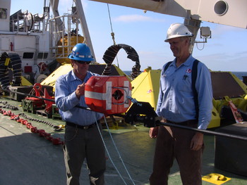
Cable Balancing – The incoming cable and the outgoing cable at each node site were installed last summer. When these cables are attached to the node, if one cable is too long it will result in loops when the Node reaches the seafloor. This will prevent burial of the cable in the seafloor and can cause cable damage if the minimum cable bend radius is violated. During the final approach to the planned node landing site, the ship attaches beacons to each cable; this enables the cable engineers to manage the shape in water (catenary) of each cable in the water column. With this information and by managing the tension on the cable, the cable engineers calculate the exact length of cable necessary to complete the node installation. Typically, short lengths of cable are removed from each cable segment as a result of these calculations.
Cable Highway – The cable highway is about 80 meters in length, extends to the entire beam of the ship and is immediately forward of the fantail on the same level. Beneath the cable highway are three large cable storage tanks. At the aft end of the cable highway there is a Linear Cable Engine and two Cable Drum Engines that are used to install and recover cable. These cable engines pull the cable out of the storage tanks and control the tension and speed of the cable as it is deployed. Along the starboard side there is the Engine Control Room, Secondary Cable Control Room, Cable Jointing Room, Test & Transmission Room and some storage space. The portside is primarily used for storage and work space. The recovery and installation of cable this year is being completed using the Cable Drum Engines. Last year’s installation of cable used the Linear Cable Engine (see photo in slideshow to left).


