- Visions18
- Visions17
- Visions16
- Visions15
- Visions14
-
Construction
- Node Installations Complete!
- Six on the Seafloor!
- New Segment 7
- Defining the SIA
- PN5A Successfully Deployed!
- PN 5A – Jointing Operations
- PN 5A Installation Continues
- On Site to Install PN5A
- Transit to Node 5A
- Port Call in Portland
- PN1D is Installed!
- Burial and Inspection Completed ...
- Humpbacks Visit
- Cable Burial Node PN1C
- Milestone: PN1C is Installed
- Photos of Final Inspection of P ...
- Another RSN Node is Born!
- Cable Burial Continues at Secon ...
- Second Node Installed!
- Splicing Node PN1B into Segment ...
- Recovering End of Segment 3
- Word for the Day: Persistence
- Major Milestone: First Node Ins ...
- Primary Node 1A Powered Up on D ...
- Recovering and Testing Cable Se ...
- OOI Primary Node Installation B ...
- Cable Installation Update
- Dolphins and Puffins and Molas, ...
- Day 51: Seabed Cable Lay Comple ...
- Dynamic Positioning
- Update on Cable Installation
- Completion of Segment 1 Burial
- Leaps and Bounds at the Shore S ...
- Segment 5 Installation Complete ...
- Laying Segment 5
- Bustling Shore Station
- At-Sea Installation Phases
- Installing the Land Cable
- TE SubCom Dependable Propulsion ...
- Divers at Work
- The Day After
- Second OOI Cable Landed
- Second Cable Landing Reschedule ...
- OOI Open House in Pacific City, ...
- The Cable has Landed!
- Last Grapnel Run Before Landing ...
- Preparing for the Cable Landing ...
- Seaplow 101
- Marine Mammal Observations
- Communicating with a Fishing Ve ...
- Cable Deployment Update
- Off Pacific City, Oregon
- Finished with First Segment
- Deploying Repeaters
- Start of First Cable Segment
- Leaving Astoria
- Meeting the Cable Ship in Astor ...
- Cable Laying Vessel Underway
- Photos of OOI Cable Loading
- Northern conduit installed
- Northern Conduit drilling compl ...
- Bubble test for the Southern Co ...
- Drilling of the Northern Condui ...
- Update on Drilling
July 2013
May 2013
December 2012
October 2012
August 2012
July 2012
April 2012
March 2012
January 2012
October 2011
September 2011
August 2011
July 2011
June 2011
March 2011
February 2011
October 2010
June 2010
May 2010
April 2010

- Visions13
- Visions12
- Visions11
- Enlighten
Related Blogs
Related Images and Videos : View All
OOI RSN Housings Pass Proof Pressure Tests
Wednesday, December 12, 2012
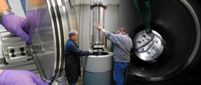

Figure 3. Randy Fabro and Larry Nielson lowering a housing into the UW School of Oceanography Pressure Test Vessel.
--Photo by Geoff Cram

Figure 6. Pause for thought. (Sign in the lobby of the building that houses the pressure test facility.)
--Photo by Geoff Cram
Systems designed to operate below the surface of the ocean must survive the relentless corrosiveness of saltwater and often great pressure as well. Protecting sensitive electrical components in sturdy, corrosion-resistant housings that have been tested on land is one of the key requirements for ensuring a successful undersea installation. Geoff Cram, OOI RSN Principal Mechanical Engineer, describes below pressure testing three such housings at a School of Oceanography facility on the UW Seattle campus in November 2012. The items tested were aircraft-grade titanium housings for the three types of secondary nodes: the Medium-Power Junction Box, the Low-Voltage Node, and the Low-Power Junction Box. These nodes serve as bridges between the OOI RSN instruments and the Primary Infrastructure, providing power and communications to the instruments, and transmitting their data back to shore.
But we weren’t ready for full-scale production yet. These housings will be made from Grade 5 titanium, a very strong and corrosion-resistant alloy that costs a lot of money and can take months to acquire. Machining is also expensive. Because we will be deploying 14 housings in two different sizes and of three types in 2013, we needed to be sure they would be up to the job before we cut any metal. After all, these housings are the heart of our program – if they don’t work, almost nothing else will. To establish beyond the shadow of a doubt that our designs are structurally sound, we needed to conduct a proof pressure test for each housing type.
Our proof pressure tests involved two brief intervals at 125% of design pressure followed by a one hour “soak” at this value, which is 6500 psi. We’re fortunate that the UW School of Oceanography has an excellent pressure test facility that is only a quarter mile from our assembly lab in Ben Hall. Adding spice to the tests, however, is the facility rule that, if the test pressure will exceed 6000 psi, the building must be evacuated by all personnel except those conducting the test. This leads to curious thoughts on the part of first-time participants and means a long day for all involved, since such tests are conducted after 6 PM.
All three types of our housings passed with flying colors. No retests were needed, and we breathed a collective sigh of relief at the end of the third run. Now it’s full speed ahead for production – deployment is only seven months away!
Special thanks to Larry Nielson, RSN Lead Field Engineer; Patrick Waite, RSN Senior Mechanical Engineer; and Randy Fabro, School of Oceanography Engineering Tech.
(Full set of photos may be found to the left on this web page, under the search bar.)